Hardware Information
Basic technical information and components
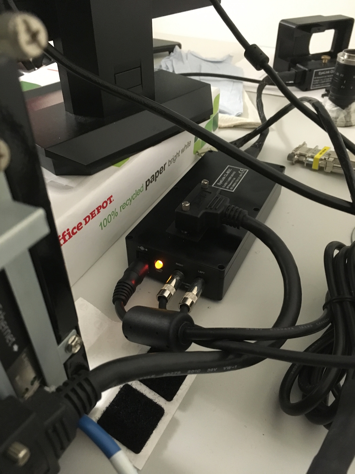
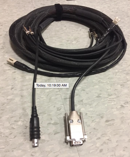
Base box that distributes power to infrared emitters and links fibre optic cable
Light colours:
Green light: All OK
Amber light (shown): Camera may not be connected to power source correctly, or fibre optic cable not properly connected
Red: ???
Top: connects base box to host PC
Phono jacks: powers infrared emitter
Fibre optic cable: clips into other end of base box and extension for fibre optic cable (or directly to the camera for testing the connection)
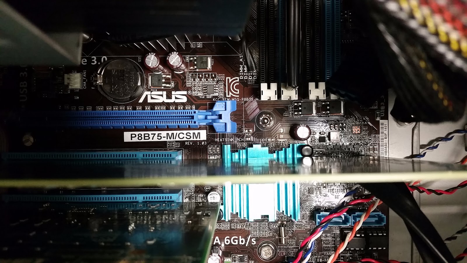
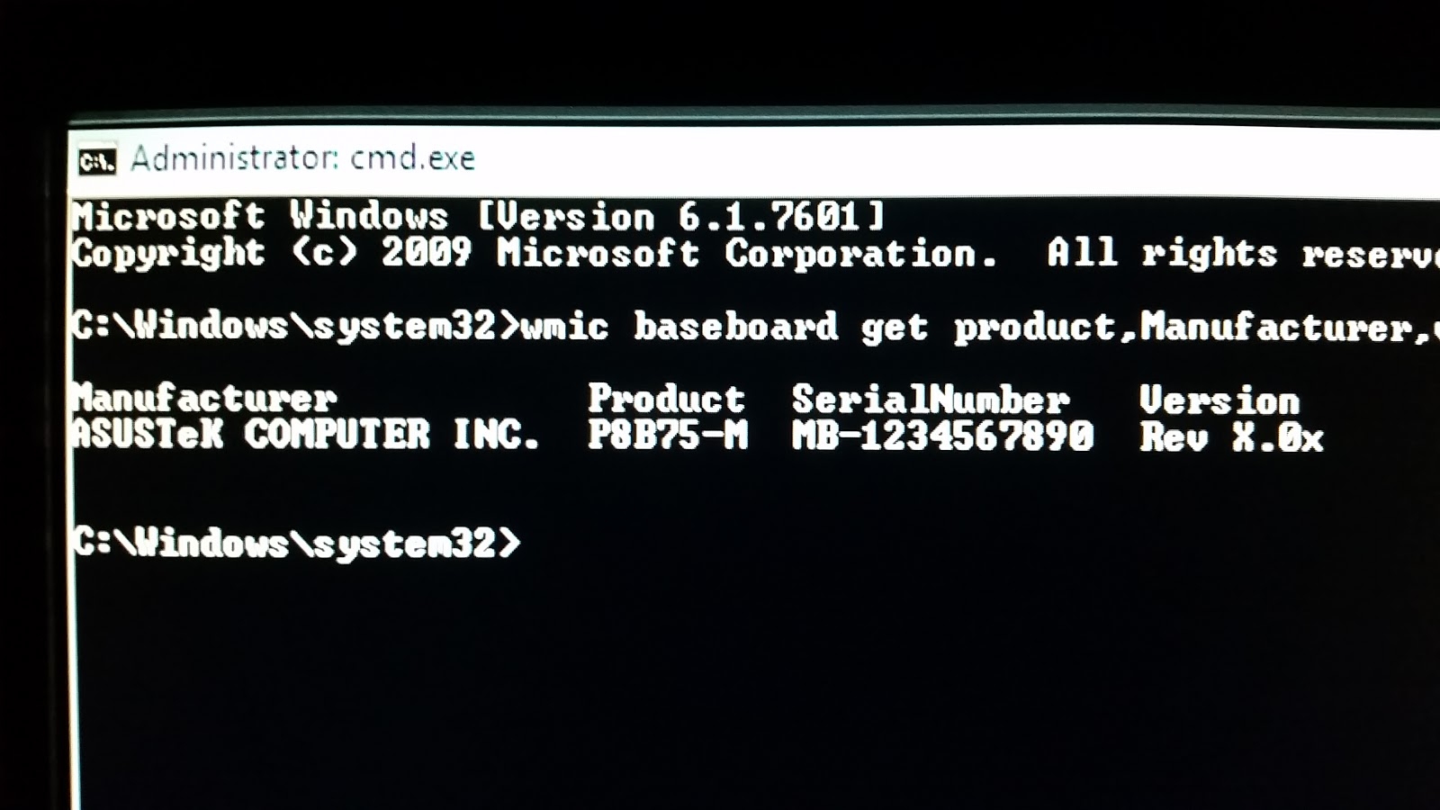
Manufacturer: ASUSTeK Computer Inc.
Product: P8B75-M/CSM
Serial number: MB-1234567890 (Retrieved from command line)
Version: Rev X.0x (Retrieved from command line)
Serial number of the base box: CLB-ZAD09
(Retrieved from the error message due to the camera not receiving power)
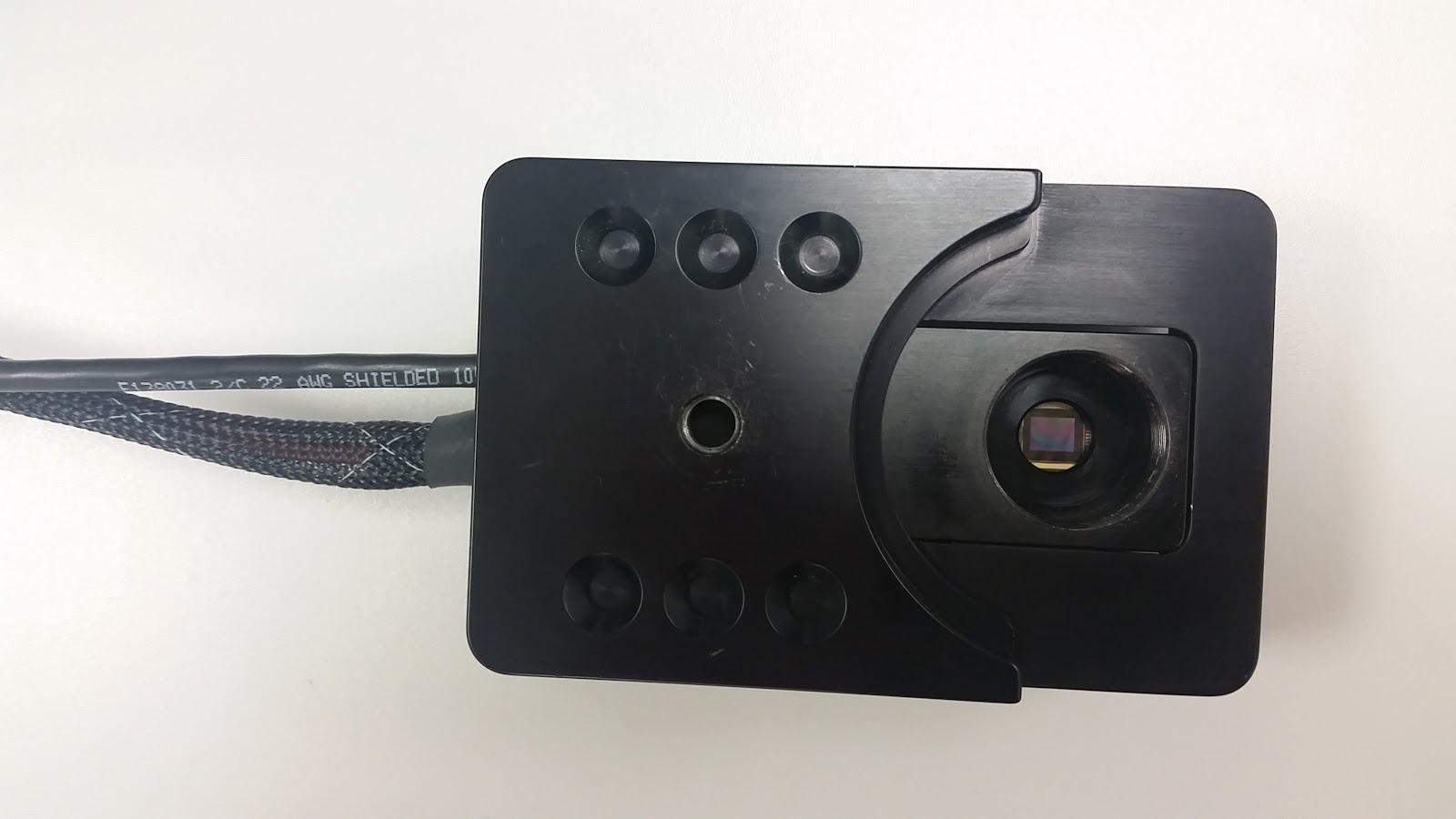
Serial number on the camera head: CL-ZAD28
Camera type: Long Range camera head
Used with an adapter for Tower and Desktop mounts
Notes on compatible accessories:
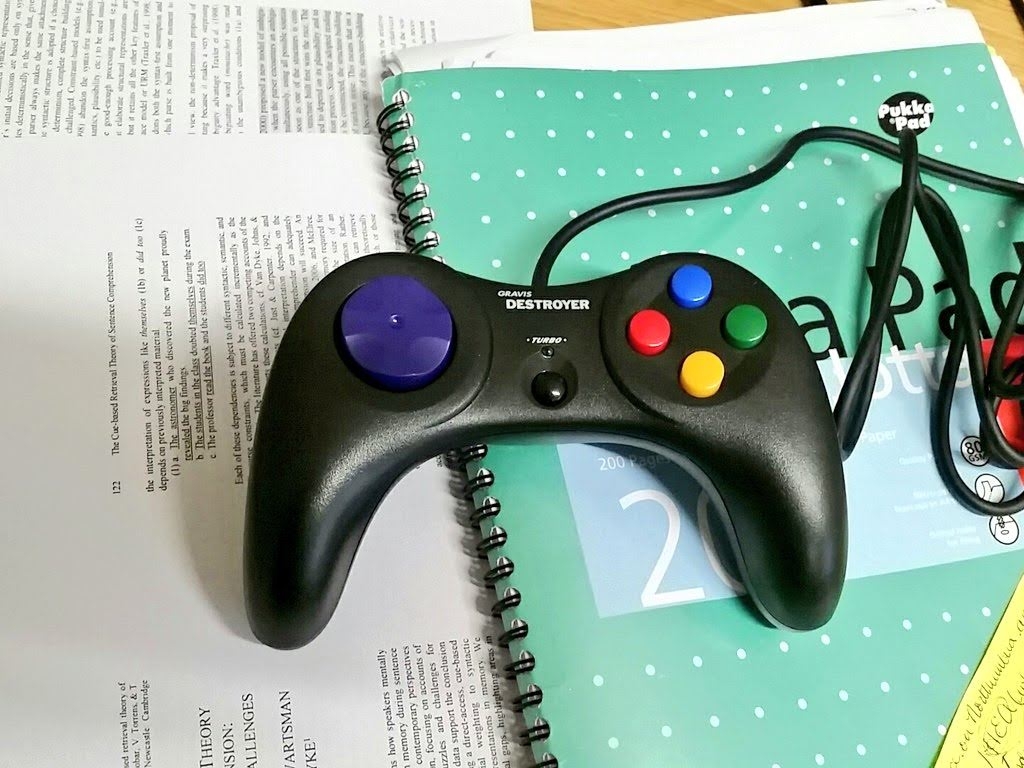
The only gamepad input that is compatible with this model is SR modified Gravis Destroyer (or SR provided parallel port button box)
This is because the host PC directly probes it for input when using EyeTrack
Gravis Destroyer
Buttons do not work in Test mode in EyeTrack, only in Run mode!
Only detectable by host PC when attached before booting up either computer
Buttons are misaligned for EyeTrack code
It may be the case that the blue/red/green/yellow buttons get realigned every time the Gravis Destroyer is unplugged/replugged into the host PC.
This can be fixed by including all four as possible ways to indicate a “No” answer.
Purple seems to be static; this can be used to indicate a “Yes” answer.
This means
output.scripthas to be manually altered to get all the buttons and intro text to be accurate.
Make sure to “Validate” the experiment before running!
Last updated